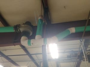
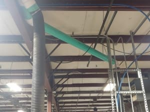
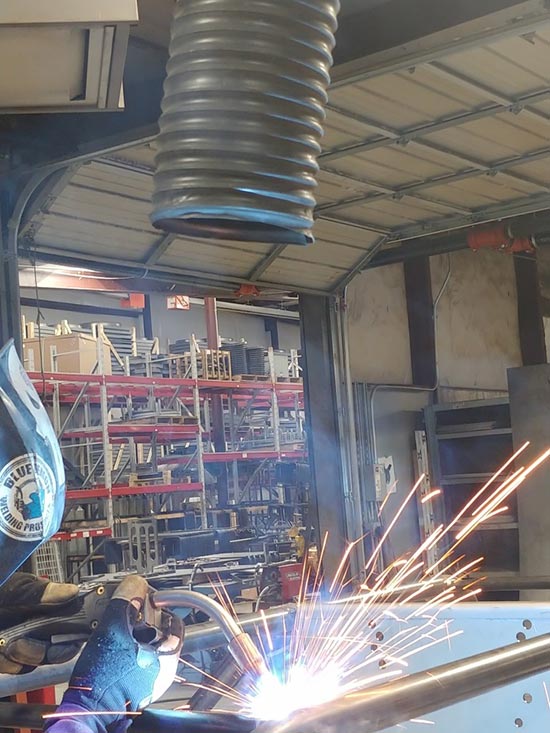
Recently, we installed blowers in our welding department to provide a more localized way to exhaust fumes by letting our welders position a hose where they wanted it. We thought we’d share some of the things we kept in mind while installing these systems for maximizing airflow.
Problem
–Welding stations to ventilate: 6
Solution
–Blowers used: 2 ADB6’s, 3 tables per blower. This is to minimize the length of the duct work and the number of branches coming off the main duct, since both of these factors reduces the amount of air that can be drawn by the blower.
–Positioning: We mounted the blower where the ductwork coming off of them would be a near-straight shot over the tables to keep bends out to keep airflow up and static pressure down. This also lowered the number of fittings needed for the job, which can lead to air leakage and a decrease in airflow.
–Materials used: We used 6” SDR35 drainage pipe as our ductwork, with spiroduct at the end as a hose for the welders to position where they need it depending on their job. We got the drainage pipe as close to the table as possible before switching to the spiroduct. Since it is flexible and not made of a smooth, hard material, it causes significant drops in airflow.
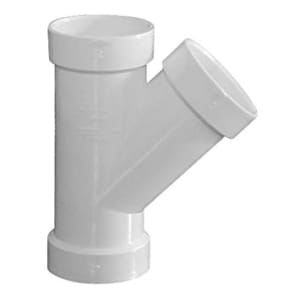
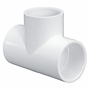
–Bends: We did what we could to keep any bends at 45 degrees, since the tighter the angle, the more disruptive it is to airflow. For the same reason we used wye fittings as branches off the main ducts instead of tees.
“Wye” fitting
“Tee” fitting
-Additional help: We already had 3 of our belt-driven exhaust fans installed on the back wall of our welding department to draw out welding fumes and for general ventilation. For this project, we custom made the panels for two of these fans to have holes to act as outlets at the end of the blower ducts. Thanks to this design; when these fans run they help draw out additional airflow from the blowers’ outlets. Now, the blowers provide localized exhausting of each welding job while the wall fans remove any excess to keep the air of our plant clean.
Measuring Your Airflow:
If you need to figure out how much CFM your fan or blower is moving, you can use an airflow meter to measure the velocity of the air, and use the formula below to turn you feet per minute (FPM) to cubic feet per minute (CFM):
CFM = FPM x Duct Cross Section Area
In our case, we had 6-inch round ducts. So after converting that to feet, we used to find the cross section area, where r is the radius of the duct, or .25 feet, making the area .196 square feet. Multiplying whatever FPM measurement you get on your airflow meter will give you your CFM.
Closing Thoughts:
Maximizing CFM is all about limiting disruptions to the airflow. While the ideal solution would have been to have a blower per table, we believe we did the practical solution, and ended up getting approximately 230 CFM per table.

